Sample Project: "Graphics Introduction"
This documentation highlights the key features of the IOGRAM Sample project "Graphics Introduction" found here.
The "Graphics Introduction" project illustrates how to use several of IOGRAM's built-in graphics features. In brief:
- We'll create some geometry
- add a floor to receive shadows
- manually change the material property of the floor
- use a sun shading component
- use a reflection probe to create reflections
- apply custom post processes to different viewports

1. Geometry Creation
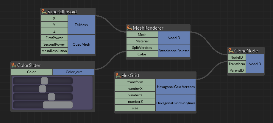
To create geometry, we use the same method as in the "Node Cloning" project. We use the super-ellipsoid component to create a mesh (increase the mesh resolution, and set "SplitVertices" to false for smooth rendering). The node is cloned and transformed using the hexagon grid.
2. Add a floor to receive shadows
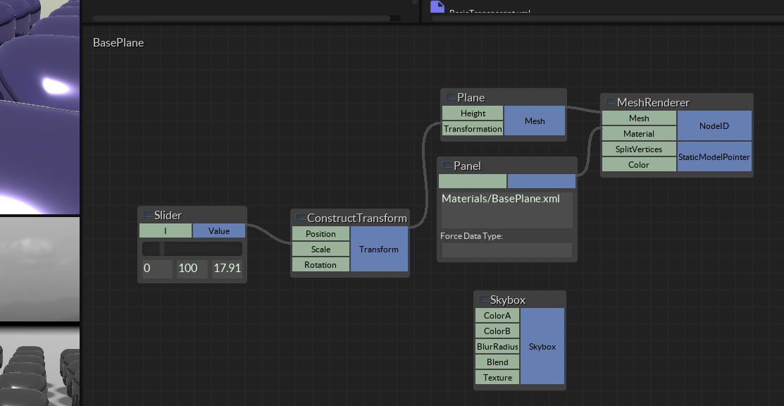
We'll be adding a sun component, so we'll want something for our geometry to cast shadows against. We create a separate graph view for the floor, by double clicking the "MyGraphView" label at the top left of the graph view, then entering a title for the new view (we used "BasePlane"). This creates a blank graph view.
To create the floor, we use the "Mesh_Plane" component. Connect it to the MeshRenderer to view it. Right-click the Height input to set a value to move the plane down. We also scaled the plane using the "ConstructTransform" component, and a slider for scale.
We also dragged the "Skybox" component on to the canvas, which changes the appearance of the skybox. To change the texture, you can right-click on the "Texture" input, and enter a path to any image file.
3. Edit material for plane
The "MeshRenderer" by default renders all geometry with a basic material found at "CoreData/Materials/BasicPBR.xml". However, we can customize the appearance of any rendered geometry by using a different material, or creating a new one. In this case, we will create a new material for the base plane.
To do this, create a copy of the BasicPBR.xml material, and save it in "Data/Materials/". We called our material "BasePlane.xml". Open up this file in your text editor of choice. You should see something like this:
<?xml version="1.0"?>
<material>
    <technique name="Techniques/PBRNoTexture.xml" quality="0" loddistance="0" />
    <parameter name="UOffset" value="1 0 0 0" />
    <parameter name="VOffset" value="0 1 0 0" />
    <parameter name="MatDiffColor" value="0.8 0.8 0.8 0.8" />
    <parameter name="MatEmissiveColor" value="0.0 0.0 0.0" />
    <parameter name="MatEnvMapColor" value="0.8 0.8 0.8" />
    <parameter name="MatSpecColor" value="0.8 0.8 0.8 0.8" />
    <parameter name="Roughness" value="1.0" />
    <parameter name="Metallic" value="0.0" />
    <cull value="ccw" />
    <shadowcull value="ccw" />
    <fill value="solid" />
    <depthbias constant="0" slopescaled="0" />
    <renderorder value="128" />
</material>
We made two edits to the material. First, we set the "Roughness" to 1.0 (from 0.2). We also set "Metallic" to 0.0 (from 0.6). This has the effect of eliminating the shinness of the plane. Save these changes, then set the "Material" input of the "MeshRenderer" component to "Materials/BasePlane.xml".
4. Use a sun shading component
Return to the main graph view (double click on the graph view label, then type in the name of the view you wish to navigate to. Note the pop-up list is not a menu bur simply a list of what views are present.
Drag the sun component on to the canvas.
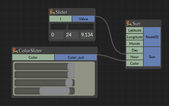
We left the "Latitude", "Longitude", "Month" and "Day" the same, and attached a 24 hour slider to the "Hour" input. We also used a slightly warm tone for the "Color".
5. Use a reflection probe to create reflections
We want to create some reflections on the ellipsoid geometry. To do this, we use the "RefletionProbe" component.
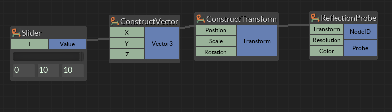
Just dragging the component on to the canvas already creates an interesting effect. Different effects can be obtained by moving the position of the probe. We do this by constructing a vector which just moves the probe upward, then using this as the "Position" input of the "ConstructTransform" component, as illustrated in the image above.
6. Use different post process effects on different viewports
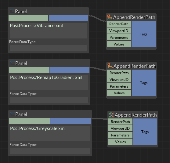
In this final step, we will create multiple viewports, and apply different post process effects to each of them using the "AppendRenderPath" component.
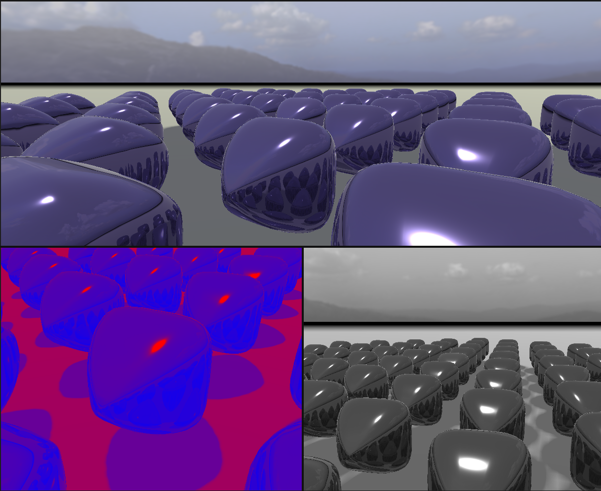
To create multiple viewports, split the scene view by clicking on the top border of the view. A menu will appear. Use the controls to split the window, and create three scene views. We'll apply a different technique to each viewport using the "AppendRenderPath" component as indicated in the image below. Note that the Viewport ID is determined by the order in which the viewport is created.